Hey guys,
We’re attempting to setup a device which is triggered by one of the auxiliary relays when the user begins using equipment. Through our testing we haven’t been able to get any current measurement from either auxiliary relay; we’ve tested various combinations of hooking up S & O terminals to W with no luck. Do we need to supply an input voltage to activate these relays? In Fabman we have the configuration of the bridge set to “Switch on when busy”. Any advice to measure these relays’ current when activated on a multimeter would be well appreciated!
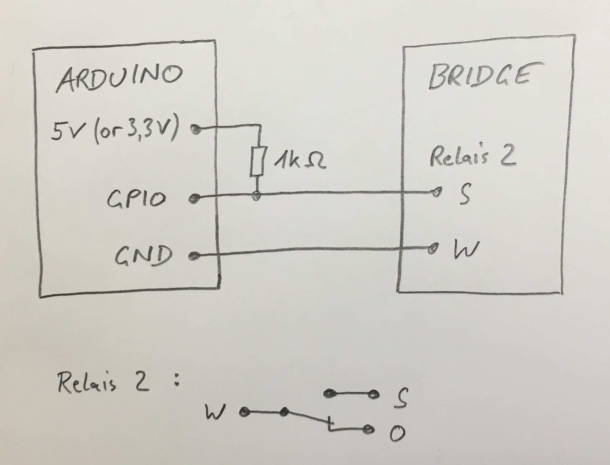
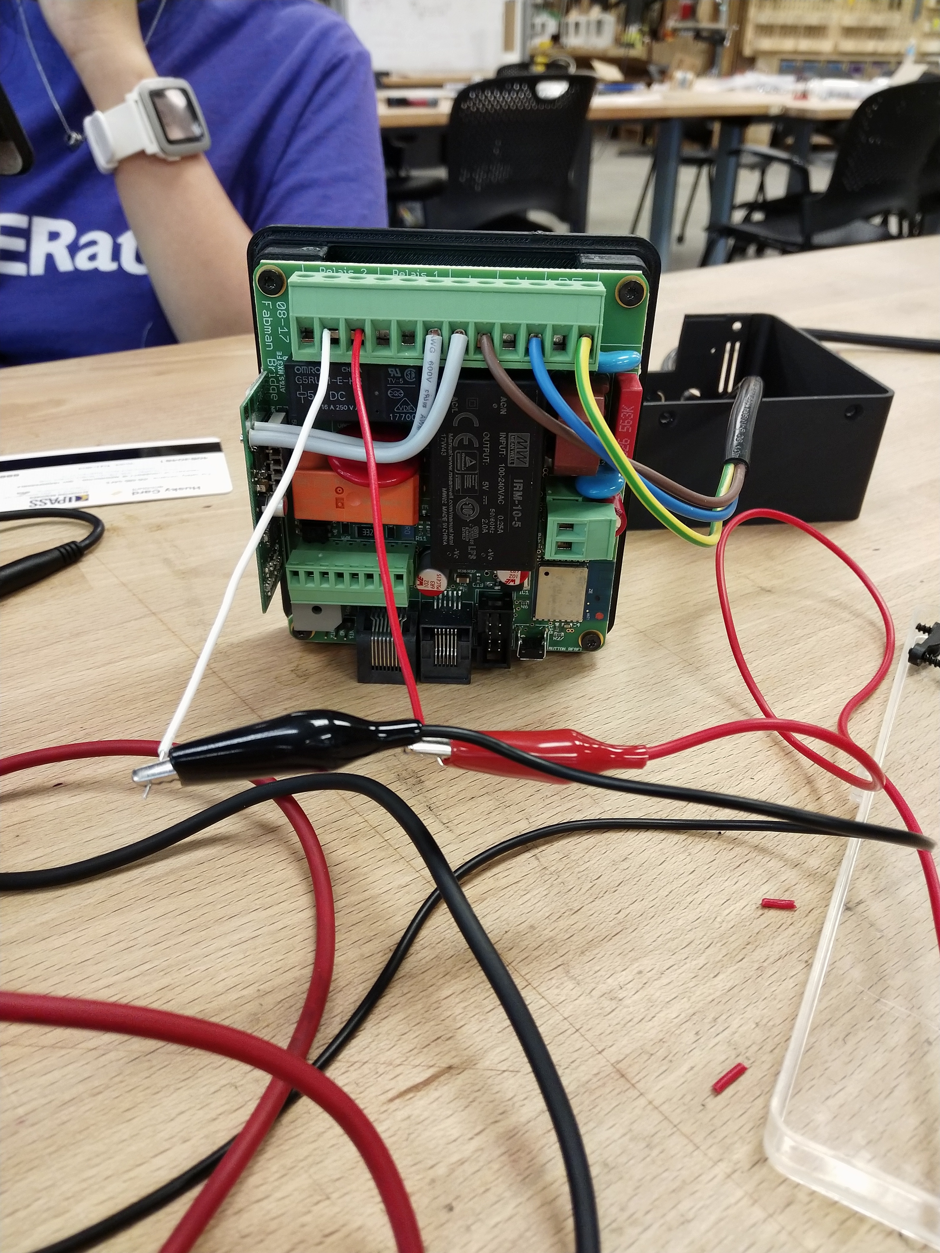
Here’s what our circuit setup currently resembles:
Though I could learn from a multimeter, I also wanted to know what voltage the relays would supply in general? The circuit diagram says 250V max. I was hoping to be able to plug this aux. relay into an Arduino, so I was thinking of creating either a voltage divider circuit, or using an opto-isolator such as the one here:
Warm regards,
Cody